
Vapour-compression
theoretical graphs
Absolute

temperature
- Entropy
A-B, Isobaric Heat
absorption in the evaporator
B-C, Isentropic
compression in the compressor (frictionless adiabatic compression in ideal
cycle)
C-D,
Isobaric Heat removal in condenser
D-A,
Constant enthalpy expansion in expansion valve
Heat
energy equivalent of work done = Heat energy rejected- heat energy received
= Area ABCDA + Area under AD
Coefficient
of performance = heat energy received/ Heat energy equivalent of work done
The
coefficient of performance for freon is about 4.7
It should
be noted that undercooling increases the heat received by moving point A to the
left increasing the refrigerant effect.
The critical point is the poiunt above which
a.
the gas will not liquify by the action of
pressure alone. This is an important temperature for refrigeration systesm
which rely on the change of state for heat transfer.
b.
The gas will not liquify by cooling alone
p-h diagram
(Mollier)

Typical
system
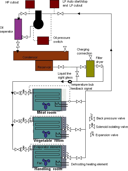
The system shown above and
described below is typical of that fitted on may ships other than it is more
common to have two low temperature rooms rather than one.
Components
Cold rooms
Meat Room-Low
temperature room typically working at -17oC
Veg/
handling room-typically working at +4oC
Compressor
Generally
of the single stage, reciprocating type. Larger systems have multple cylinders
with an unloader system using the suction pressure as its signal.
Refrigerant is compressed in the
compressor to a pressure dependent upon the temperature of the cooling water to
the condenser, and to a lesser extent the volume of gas in the system. As the
temperature of the cooling water rises so does the minimum temperature of the
refrigerant liquid rise, and with it the corresponding saturation pressure.
Compressor
safety devices
The
compressor is protected by three safety switches;
The OP switch or Oil
Differential Pressure switch compares the measured lubricating oil pressure
to the Suction (crankcase) pressure. Should the differential pressure fall
below a pre-set minimum (about 1.2 bar) then the compressor will trip and
require a manual reset to restart. A time delay is built into the circuit to
allow sufficient time for the lubricating oil pressure to build up when
starting before arming the circuit.
The HP or High Pressure switch,
is fitted to the outlet of the compressor before the isolating valve. On over
pressurisation (dependent on the refrigerant, up to about 24bar bar for R22)
the switch will trip the compressor and a manual reset is required before
restart.
The LP or Low Pressure switch
when activated ( at about 1 bar for R22) will trip the compressor and require a
manual reset before the compressor can be restarted.
Compressor
control devices
This
normally takes the form of an LP cut out pressure switch with automatic reset
on pressure rise. The cut out set point is just above the LP trip point say at
about 1.4bar. An adjustable differential is set to about 1.4bar to give a cut
in pressure of around 2.8 bar. The electrical circuit is so arranged that even
when the switch has reset, if no room solenoid valves are open the compressor
will not start. This is to prevent the compressor cycling due to a leaky
solenoid valve.
In addition to this extra LP
switches may be fitted which operate between the extremes of the LP cut in and
cut out to operate compressor unloaders.
Some modern systems contain a
rotary vane compressor with variable speed (frequency changing) control
Oil
Seperator

The purpose of the oil seperator,
situated on the compressor discharge line, is to return oil entrained in the
gas, back to the compressor sump.
The oil return may be float controlled
as shown, electric solenoid controlled on a timer, or uncontrolled with a small
bore capillary tube allowing continuous return.
With all of these methods a shut
off valve is fitted between separator and compressor to allow for maintenance.
The oil gas mix enters the
separator where it is made to change direction, the heavier oil droplets tend
to fall to the bottom.
Condensor
Generally
a water cooled tube cooler.A safety valve and vent are fitted. The purpose of
the vent is to bleed off non-condensibles such as air which can enter the
system when the suction pressure is allowed to fall below atmospheric or can be
contained within the top up gas. The presence of non-condensibles is generally
indicated by a compressor discharge pressure considerably above the saturation
pressure of the refrigerant.
The coolant flow to the condenser
is sometimes temperature regulated to prevent too low a temperature in the
condenser which can effect plant efficiency due to the reduction in pressure.
Below the condenser, or sometimes
as a separate unit, is the reservoir. Its purpose is to allow accurate gauge of
the level of refrigerant in the system. In addition to this it also allows a
space for the refrigerant liquid when the system is 'pumped down'. This refers
to the evacuation of the refrigerant gas to the condenser to allow maintenance
on the fridge system without loss. For systesm not fitted with a reservoir, a
sight glass is sometimes incorpotated on the side of the condenser. Care should
be given to ensuringthat the liquid level is not too high as this reduces the
surface area of the cooling pipes available for condensing the liquid and can
lead to increased discharge pressures.
Sight Glass
Often of
the Bulls eye form. This allows the operator to ensure that it is only liquid,
and not a liquid/gas mix going to the expansion valves. On some designs a water
indicator is incorporated, this is a coloured ring in contact with the liquid,
when water is detected it changes colour, typically from pink to blue.
Filter Drier
Can be
either a compacted solid cartridge or bags of dessicant. The main purpose of
this unit is to remove the moisture from the refrigerant.
Moisture cause two main problems.
Firstly it can freeze to ice in the evaporator and cause blockage. Secondly it
can form acids by reaction with the freon refrigerants. This acid attacks the
copper in the lines and deposits its in other parts of the system. This can
become particularly troublesome when it is deposited on the compressor
mechanical seal faces leading to damage and leakage.
Fine particles which could
possible block the expansion valve are removed.
Topping up
the refrigerant
A filling
connection is fitted in way off the filter dryer, either directly onto it or on
the inlet line after the inlet shut off valve. This allows additional
refrigerant to be introduced into the system via the dryer element.
The normal procedure is to shut
or partially shut the inlet to the filter. The compressor is now sucking from
the system and delivering to the condenser where the gas liquifies. The filter
dryer is on the outlet from the condenser therefore with its inlet valve shut
the liquid level begins to rise in the reservoir. As the only gas entering the
system is now coming from the top up line the compressor will tend to reduce
the suction side pressure as it evacuates the system into the condenser.
The inlet valve can be briefly
opened to allow more refrigerant into the system.
Thermostat
and Solenoid Valve
These two
elements form the main temperature control of the cold rooms.
The Thermostat is set to the
desired temperature and given a 3 to 4 degree differential to prevent cycling.
When the temperature in the room reaches the pre-set level the thermostat
switch makes and the room solenoid is energised allowing gas to the refrigerant
liquid to the expansion valve.
A manual overide switch is fitted
as well as a relay operated isolating contact which shut the solenoid when the
defrost system is in use.
System
operation
Assume
that the rooms are all warm and the compressor is running with all the solenoid
valves open supplying refrigerant to the respective expansion valve and
evaporator.
Should one or two rooms be down
to temperature the solenoids close thus reducing the volume of gas returning to
the compressor. The suction pressure drops and the compressor unloads. If more
rooms shut down then the suction pressure will drop to cut out point and the
compressor will stop. When the rooms warm the solenoids open again, refrigerant
passes back to the compressor, the suction pressure rises and compressor
starts. With more rooms opening, the suction pressure increases and the
compressor loads up more cylinders.
Thermostatic
expansion valve-

The purpose of this valve is to
efficiently drop the pressure of the refrigerant. It achieves this by passing
the liquid through a variable orifice giving a constant enthalpy pressure drop.
The refrigerant at lower pressure has a corresponding lower boiling point
(saturation temperature). Undercooling in the condenser increases the
efficiency of the plant by allowing more heat to be absorbed during the
vapourisation process. In addition it also reduces the internal heat absorption
process that occurs during the expansion stage which is due to a small degree
of flash off as latent heat (of vaporisation) is absorbed from surrounding
liquid to reduce the temperature of the bulk liquid to the new corresponding
saturation temperature for the reduced pressure
By this process of boiling
(vapouriation) and latent heat absorption i.e. change of state, the refrigerant
removes heat from the cold rooms.
The expansion process is
controlled by the action of the bellows and push pins acting on the orifice
valve plate. The bellows is controlled by a bulb which measures the temperature
of the gas at outlet from the evaporator. To ensure no liquid passes through to
the compressor, the expansion valve is set so that the gas at outlet from the
evaporator has 2 to 3 degrees of superheat.
For larger systems where a
significant pressure drop exists across the evaporator it is necessary to fit a
'Balance line'. This is a small bore tube which feeds the outlet
pressure back to the thermostatic valve 'motor' element. Therefore the measured
temperature is directly related to the superheat temperature at outlet
pressure.
Some systems are designed so 5%
liquid is available through the evaporator to coat the internal surfaces of the
tubes increasing heat transfer efficiency.
Author Note
Careful note should be taken that
system temperatures are set by the room solenoid and not by the expansion valve
which are generally factory set and do not require adjustment.
This may seem an obvious fact but you
would be amazed as to the number of broken valve plates removed from
compressors due to the mal adjustment of the superheat.
Adjustment of the back pressure valves-
which if they have not been touched by ships staff should be unnecessary- can
allow better system balance especially when certain rooms are being starved of
gas.
Back
pressure regulator valve
This
valve is fitted to the higher temperature rooms, vegetable and flour (+5oC)
only and not to the Meat and Fish rooms (-20oC).
They
serve two main purposes.
Firstly when all solenoid valves
are opened they act as system balancing diverters, that is they restrict the
liquid flow to the rooms which can be kept at the higher temperature and
deliver the bulk to the colder rooms.
Secondly they serve to limit the
pressure drop across the expansion valve by giving a set minimum pressure in
the evaporator coil. This in turn limits the temperature of the refrigerant
thereby preventing delicate foodstuffs such as vegetables from being damaged by
having air at very low temperatures blown over them. Ultimately they may also
be set to provide a safety limit to the room temperature by restricting the
pressure to give a corresponding minimum saturation temperature of 0oC.
Oil
rectifier

In
some installations there is a tendency for oil to collect in the evaporator
under certain conditions such as low load when the speed of movement and
agitation of the evaporating refrigerant are insufficient to keep the oil
moving. To prevent loss of oil from the sump to the system, an oil rectifier
may be fitted. The oil is automatically bled from the evaporator to a heat
exchanger in which liquid refrigerant mixed with the oil is vaporised. The heat
for vaporising the refrigerant is obtained by passing warm liquid freon from
the condenser, through the heat exchanger. Vapour and oil are passed to the
compressor where oil returns to the sump while the freon passes to the
compressor suction. The regulator is thermostatically controlled valve which
operates in the same way as the expansion valve on the main system. It
automatically bleeds the oil from the evaporator so that the gas leaves the
heat exchanger in a superheated condition.
Defrost
system
Moisture
freezes onto the evaporator eventually causing a restriction and reducing the
efficiency of the plant. This must be periodically removed. For Veg and Flour
rooms, were not restricted to 0oC minimum by the back pressure
valve, this is carried out once per day. For the Meat and Fish rooms this has
to be carried out two or more times. Due to the low temperature in the rooms it
is necessary to fit a drain heater.
When on defrost the solenoid
valve is shut and the fan is off. On some systems at end of defrost the solenoid
valve is opened momentarily before the fan is started. This allows moisture to
be snap frozen onto the surface of the element, creating a rough increased
surface area and thereby increasing the heat transfer rate.
Author note
Care should be taken after loading any
great quantity of stores especially into the vegetable rooms. The fresh stores
tend to sweat and icing up of the evaporator can become rapid. The only
solution is constant monitoring and defrosting as soon as necessary.
Effects of
under and over charge
The
effects of overcharge are a full condenser/receiver gauge glass. System
pressures are not effected until highly overcharged when a possibility of
excessive HP pressure exists. Undercharge causes failure to maintain cold room
temperatures and compressor cycling. Compressor cycling is caused by there
being insufficient gas to maintain the compressor loaded even with all room
solenoids open. In extreme the compressor will cut in and out. Undercharge is
detected by low levels in the condenser/receiver gauge glass/ bubbles in liquid
sight glass, compressor cycling and low suction pressures.
Troubleshoot
A ship had real problems with the control
of room temperatures, one room in particular. attempts to 'balance' the system
using the back pressure valves usually resulted in rooms starved of gas and/or
the compressor tripping on Low Pressure trip. It turned out that sag on one or
two of the liquid line pipes allowed oil and debris to build up in this section
and restrict flow.
On another ship the lagging around a
penetration piece had been damaged and water had got behind it into the
insulation. This liquid had frozen and exerted a crushing force on the pipe
sufficient to severely restrict the flow. This was only found after some
searching as before the lagging was removed nothing wrong could be seen.


